This topic is more difficult than I previously expected. I have spend a whole week digest every piece of mathematics. I use my arms everyday but never thought a robotic arm hides so many transformation matrice!
Kinematics
Industrial robot arm: KUKA KR 210

Kinematics is a branch of classical mechanics that studies how things move without considering the forces required to produce the motion. Several important concepts:
- reference frames
- generalized coordinates
- degree of freedom
- homogeneious transform
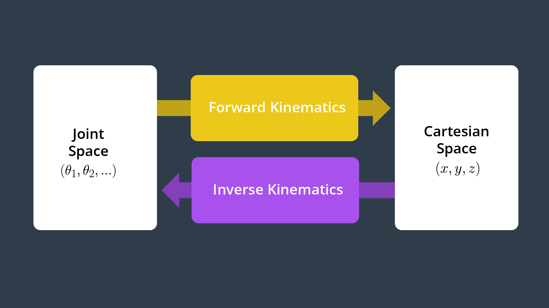
- forward kinematics: joint space (theta1,theta2) -> Cartesian space (x,y,z)
- inverse kinematic
To fully describe the configuration of a rigid body in 3-dimentional free space, you will need to specific 6 coordinates.
Joint types:
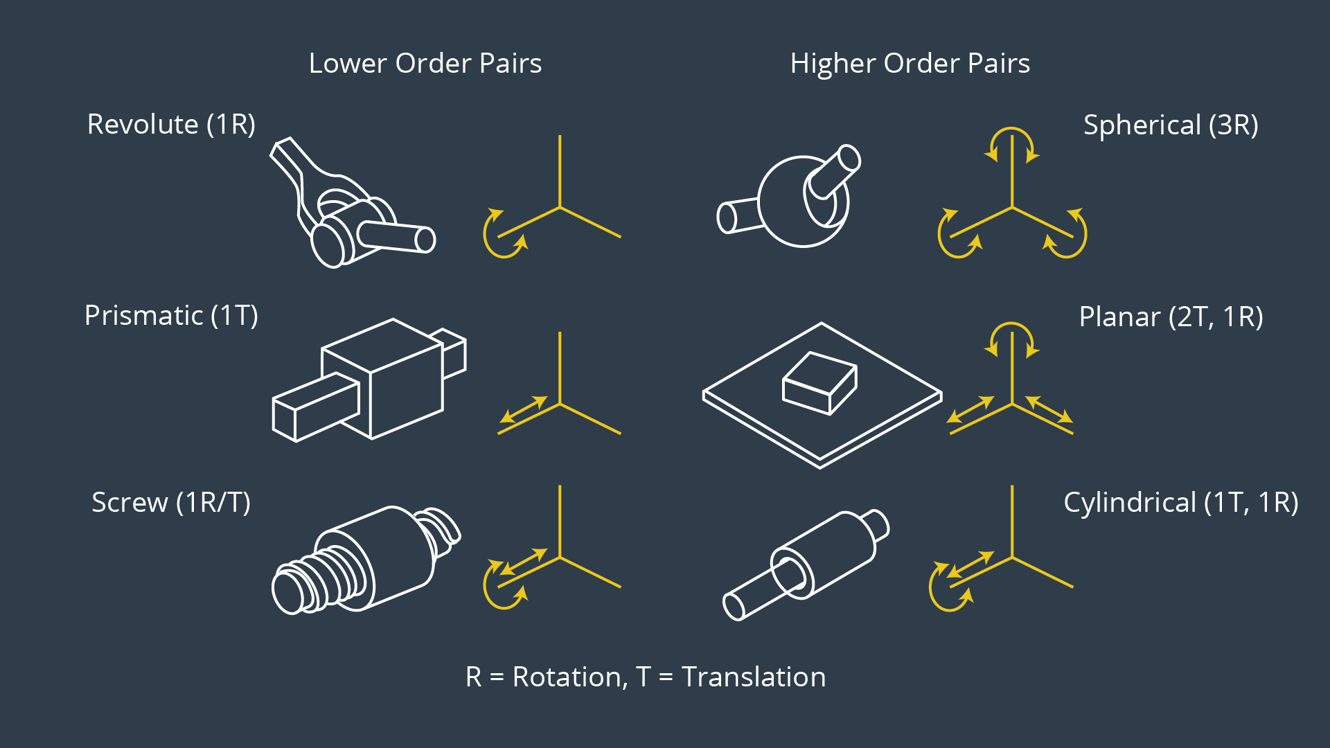
Rovolute Joint: It rotate along a specific axis.
Prismatic joint: provides a linear sliding movement between 2 bodies, and is often called a slider, as in the slider-crank linkage.
End effector: the device at the end of a robotic arm, designed to interact with the environment.
Joints can be grouped into lower order pairs having one DoF and higher order pairs offering two or three DoF. For serial manipulators (a.k.a., robot arm or kinematic chain), the most common joint types are revolute and prismatic allowing one rotational and one translational DoF, respectively.
Two rigid bodies in free space connected by a one DoF revolute joint would only have a total of 6 +1 = 7 DoF. For modeling purposes, higher order pairs are always replaced by a collection of lower order pairs, e.g. the revolute and prismatic Joint, each with 1 DoF. For serial manipulators with only revolute and/or prismatic joints, the number of degrees of freedom is always equal to the number of joints.
A typical serial manipulator has 6 degree of freedom: the first 3 joints control the location of the wrist center, while the last 3 only control the orientation of the end effector. A sphereical wrist has 3 DoF.
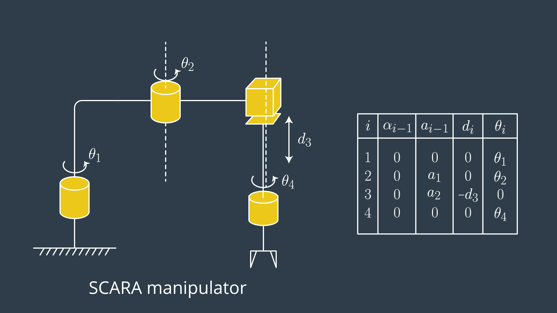
With only revolute and prismatic joints, there are only 8 possible permutations of arm types. But only 4 types are commonly used in industry: Cartesian (PPP), Cylindrical (RPP), Anthropomorphic (RRR), Scara/Spherical(RRP).
workspace: the set of all points reachable by the end effector.
What this course is about?
Given a robotic arm, we can know the parameters of the orientation and relative distance of each joint,
Forward kinematic problem: assume we know the rotation angle and translation distance, how can we express end effector’s position, either in analytical formula or numerical values?
Inverse Kinematic problem: we alway know the target position, how can we derive the angle and translation distance for each joint?
2.3 Rotation matrix
Rotation matrix solves the problems that 2 frames have different orientations.
Given: point (ux,uy) in frame B, angle theta from frame A to B.
Ask: what’s (vx,vy) in frame A for the same point? frame A can be considered as the orginal frame or the world map.
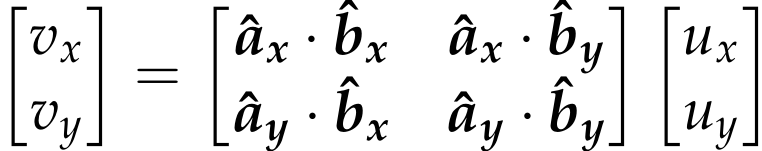
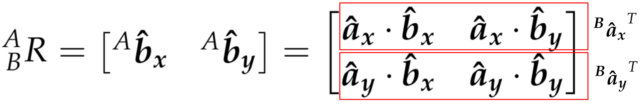
The rows of R are the projection of the A-frame onto B.
Features of Rotation matrices:
- orthonormal matrices
- The transpose is equal to its inverse
- the determinant is equal to 1
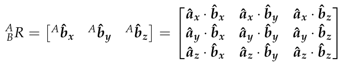
3D Rotation matrix: elementary rotation.
2.6 Rotations in Sympy
from sympy import symbols, cos, sin, pi, simplify
from sympy.matrices import Matrix
import numpy as np
q1, q2, q3, q4 = symbols('q1:5')
R_x = Matrix([[ 1,              0,        0],
              [ 0,        cos(q1), -sin(q1)],
              [ 0,        sin(q1),  cos(q1)]])
R_y = Matrix([[ cos(q2),        0,  sin(q2)],
              [       0,        1,        0],
              [-sin(q2),        0,  cos(q2)]])
R_z = Matrix([[ cos(q3), -sin(q3),        0],
              [ sin(q3),  cos(q3),        0],
              [ 0,              0,        1]])
2.7 composite rotation
Euler angles: a system to describe a sequence of rotations. The orientation of any rigid body with respect to some fixed reference frame can always be described by 3 elementary rotations in a given sequnece.
Several convection:
- Intrinsic rotation, body fixed. use new axis. post-multiply
- Extrinsic rotation, fixed axis. use original axis. Pre-multiply
Rotations do not obey the commutative law of multiplication. The order matters.
2.8 from rotation matrix to Euler Angle
Consider the extrinsic (i.e., fixed axis) X-Y-Z rotation sequence. The composite rotation matrix is,
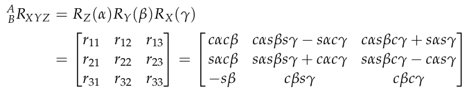
An inverse inferring to get  is possible. e.g.
 %2Ccos(%5Cbeta))%3D%20atan2(-r31%2C%20%5Csqrt()))
mport numpy as np
from sympy.matrices import Matrix
from sympy import symbols, atan2, sqrt
# Conversion Factors
rtd = 180/np.pi
dtr = np.pi/180
# Fixed Axis X-Y-Z Rotation Matrix
R_XYZ = Matrix([[],[],[]])
r11,r21,r31 = R_XYZ[:,0]
r32,r33 = R_XYZ[2,1:3]
### Euler Angles from Rotation Matrix
alpha = atan2(r21, r11) * rtd
beta  = atan2(-r31, sqrt(r11*r11 +r21*r21)) * rtd
gamma = atan2(r32, r33) * rtd
2.9 Translations
Note that translation only applies to different frame with the same orientation.
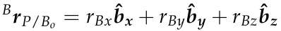
The goal then is to describe P relative to Ao, 
Because both frames have the same relative orientation, describing P relative to Ao only requires simple vector addition:
2.10 Homogeneous Transform
simultaneously rotated and translated with respect to each other:

The marix representation is designed as:
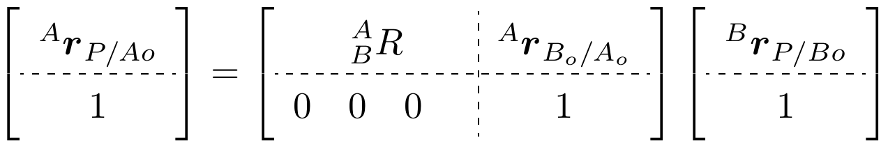
To be more specific:
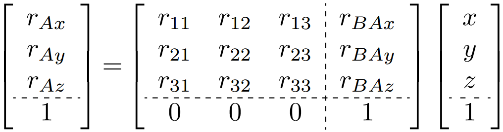
The 4x4 matrix called a homogeneous transform.
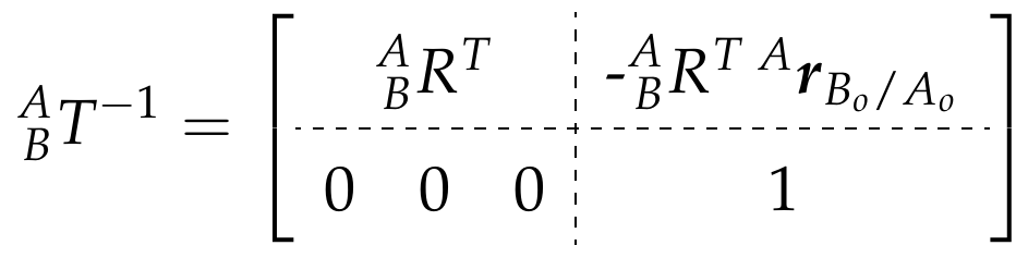
The inverse transform from B to A is:
2.11 Composition of Homogeneous Transforms
Intrinsic rotation, post multiply. The interesting thing is you treat the point as a static point, only the reference frame is changed.

2.12 DH parameter (KR 10)
In general, each transform would require six independent parameters to describe frame i relative to i-1, three for position and three for orientation.
In 1955, Jacques Denavit and Richard Hartenberg proposed a systematic method of attaching reference frames to the links of a manipulator that simplified the homogeneous transforms. Their method only requires four parameters to describe the position and orientation of neighboring reference frames.
Several modifications have been made to the DH method. The four most common sources are listed below,
- Waldron, KJ. A study of overconstrained linkage geometry by solution of closure equations, Part I: A method of study (1973). Mech. Mach. Theory 8(1):95-104.
- Paul, R. (1982). Robot Manipulators: Mathematics, Programming and Control (MIT Press, Cambridge, MA)
- Craig, JJ. (2005). Introduction to Robotics: Mechanics and Control, 3rd Ed (Pearson Education, Inc., NJ)
- Khalil, W and Dombre, E. (2002). Modeling, Identification and Control of Robots (Taylor Francis, NY)
In this course, we will be using the convention described in John J Craig’s book.
The homogeneous transform from frame i-1 to frame i is constructed as a sequence of four basic transformations, two rotations and two translations as follows:

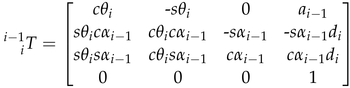
The parameter names and definitions are summarized as follows:
- αi−1 (twist angle) = angle between Z^i−1 and Z^i measured about X^i−1 in a right-hand sense.
- ai−1 (link length) = distance from Z^i−1 to Z^i measured along X^i−1 where X^i−1is perpendicular to both Z^i−1 to Z^i
- di (link offset) = signed distance from X^i−1 to X^i measured along Z^i. Note that this quantity will be a variable in the case of prismatic joints.
- θi (joint angle) = angle between X^i−1 to X^i measured about Z^i in a right-hand sense. Note that this quantity will be a variable in the case of a revolute joint.
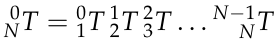
there is only one parameter that is variable (either θi or di), the link length and twist angle are constants.Thus, for the entire transform from base link to end effector,  , there are only n-variables.
An example of an actual SCARA robot (RRPR) is the KUKA KR10, which is suitable for pick and place operation.
Detailed explanation refers to section 13-16.
2.17 Forward/Inverse Kinematics
Two approaches to solve IK problem:
- numerical/Newton_Raphson algorithm: guess and iterate. different initial conditions must ben used, no guarantee the algorithm will converge
- analytical/closed-form solution
Fortunately, most industrial serial manipulators satisfy the conditions solvable by the 2nd approach. In particular, the last 3 joints are revolute joints which form a spherical wrist with a wrist center (WC). Such design kinematically decouples the position and orientation of the end effector. So the problem is divided into 2 basic steps.
1st, get the wrist center position in the base frame. The confusing thing here is that  is in the frame 6. We intentional manipulate the frame EE so these two align (same orientation) and simply becomes (0, 0, -d).
$^0r{EE/0} =[^0_6R,^0r{WC/0}]\times[^6r{EE/WC},1]^T=^0_6R\times ^6r{EE/WC}+^0r_{WC/0} $
$\rightarrow ^0r{WC/0} =^0r{EE/0}-^06R\times ^6r{EE/WC}=(px,py,pz)-d(r13,r23, r33) $
2nd, calculate the angles of first 3 joints by the Wrist Center using cosine laws
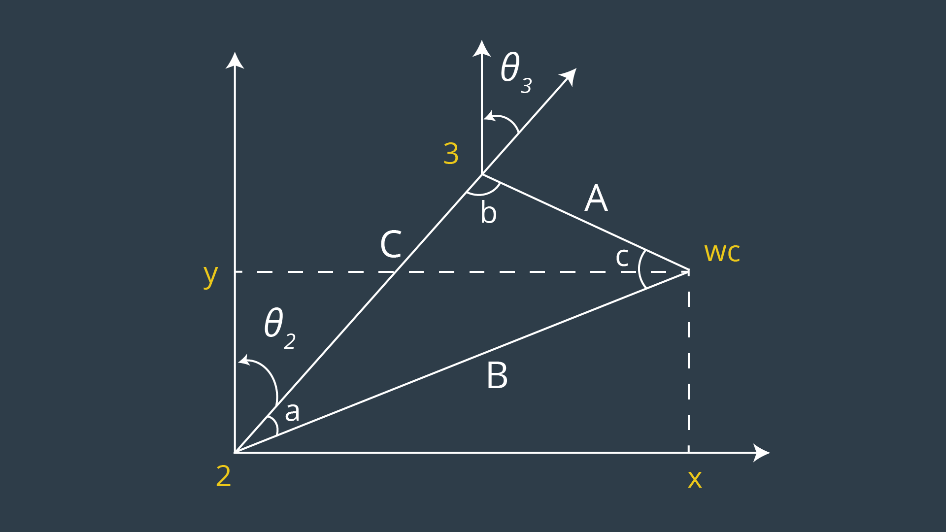
With these 3 angles, calculate the  , then get
  , the remaining angles can be calculated by the matrix element.
R3_6 = R0_3.inv("LU") * ROT_EE
theta4 = atan2(R3_6[2,2], -R3_6[0,2])
theta5 = atan2(sqrt(R3_6[0,2]*R3_6[0,2] +                                         R3_6[2,2]*R3_6[2,2]),R3_6[1,2])
theta6 = atan2(-R3_6[1,1],R3_6[1,0])
project
walk-through: https://www.youtube.com/watch?v=Gt8DRm-REt4
solution codes at time 7:20
project steps:
- setup your environment
- explore the forward_kinematics with Kuka KR210 to learn more about the robot’s geometry and derive DH parameters
- Once you have the DH parameters, run the complete pick and place project in demo mode to get an understanding of the complete project scenario.
- perform Kinematic Analysis of the robot and derive equations for individual joint angles. In addition, you will write the actual Inverse Kinematics code inside of
IK_server.pyfile with proper comments - make a brief writeup report. The github repository has a
writeup_template.mdthat can be used as a guide.
tools:
- Gazebo, a physics based 3D simulator extensively used in the robotics world:
- RViz, a 3D visualizer for sensor data analysis, and robot state visualization:
- Moveit!, a ROS based software framework for motion planning, kinematics and robot control:
While your python script only solves IK for a specific 6DOF (6 joints) robot arm (Kuka KR210), there are generalized libraries and plugins which can be used to solve IK for different types of robots. A couple of widely used solutions are:
- The Kinematics and Dynamics Library (KDL) developed by orocos
- IKFast Solver by OpenRAVE
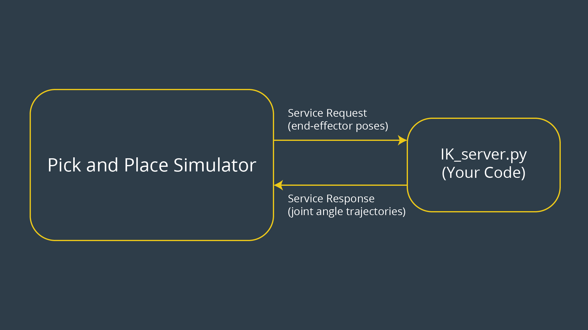
Inverse Kinematics: given a list of end-effector poses, calculate joint angles.
demo
set
/kuka_arm/launch/inverse_kinematics.launch ‘s related flag to true.$ echo "export GAZEBO_MODEL_PATH=~/catkin_ws/src/RoboND-Kinematics-Project/kuka_arm/models" >> ~/.bashrc
# write model path variable into bash file
$ gzserver
$ gzclient
$ gazebo # run both
$ roscore
$ rosrun rviz rviz
$ roslaunch kuka_arm load_urdf.launch
# in Global Options, change world to base_link
$ roslaunch kr210_claw_moveit demo.launch
$ cd ~/catkin_ws/src/RoboND-Kinematics-Project/kuka_arm/scripts
$ ./safe_spawner.sh # begin demo, it acutally did:
# roslaunch kuka_arm target_description.launch
# roslaunch kuka_arm cafe.launch
# roslaunch kuka_arm spawn_target.launch
# roslaunch kuka_arm inverse_kinematics.launch
$ roslaunch kuka_arm forward_kinematics.launch
$ rosrun tf tf_echo base_link link_6
# position and orientation data of 2 frames
Unified Robot Description Format or urdf, is an XML format used in ROS for representing a robot model. We can use a urdf file to define a robot model, its kinodynamic properties, visual elements and even model sensors for the robot. URDF can only describe a robot with rigid links connected by joints in a chain or tree-like structure. It cannot describe a robot with flexible links or parallel linkage.details: https://classroom.udacity.com/nanodegrees/nd209/parts/7b2fd2d7-e181-401e-977a-6158c77bf816/modules/8855de3f-2897-46c3-a805-628b5ecf045b/lessons/91d017b1-4493-4522-ad52-04a74a01094c/concepts/304b7bc0-6fe8-4614-bd09-4a545665adad
within
kuka_arm/urdf/:kr210.urdf.xacro- this file contains all the robot specific information like links, joints, actuators, etc.kr210.gazebo.xacro- this file contains gazebo specific information like robot material, frictional constants, and plugins to control the robot in gazebo
MoveIt! does not have an inbuilt motion planning algorithm. Instead it provides a convenient plugin interface to communicate with and use various motion planning libraries.Moveit! utilizes a special ROS Service to establish a request-response relationship with any given motion planner.
At various stages in the process of motion planning, Moveit! needs to convert the joint_state of the robot into the end-effector pose using Forward Kinematics, and vice-versa using Inverse Kinematics.
While your python script only solves IK for a specific 6DOF robot arm (Kuka KR210), there are generalized libraries and plugins which can be used to solve IK for different types of robots. A couple of widely used solutions are:
- The Kinematics and Dynamics Library (KDL) developed by orocos
- IKFast Solver by OpenRAVE
The important detail to remember is that our URDF model does not follow the DH convention; the frames from your DH parameter table will NOT always match the default orientation of the KUKA arm in RViz and/or gazebo.
IK_debug.py
A typical test case is
[[EE position],[EE orientation as quaternions]],[WC location],[joint angles] with size of 3,4,3,6. The first 2 vectors can used as input, and the last 2 vectors can be used for checking the IK results.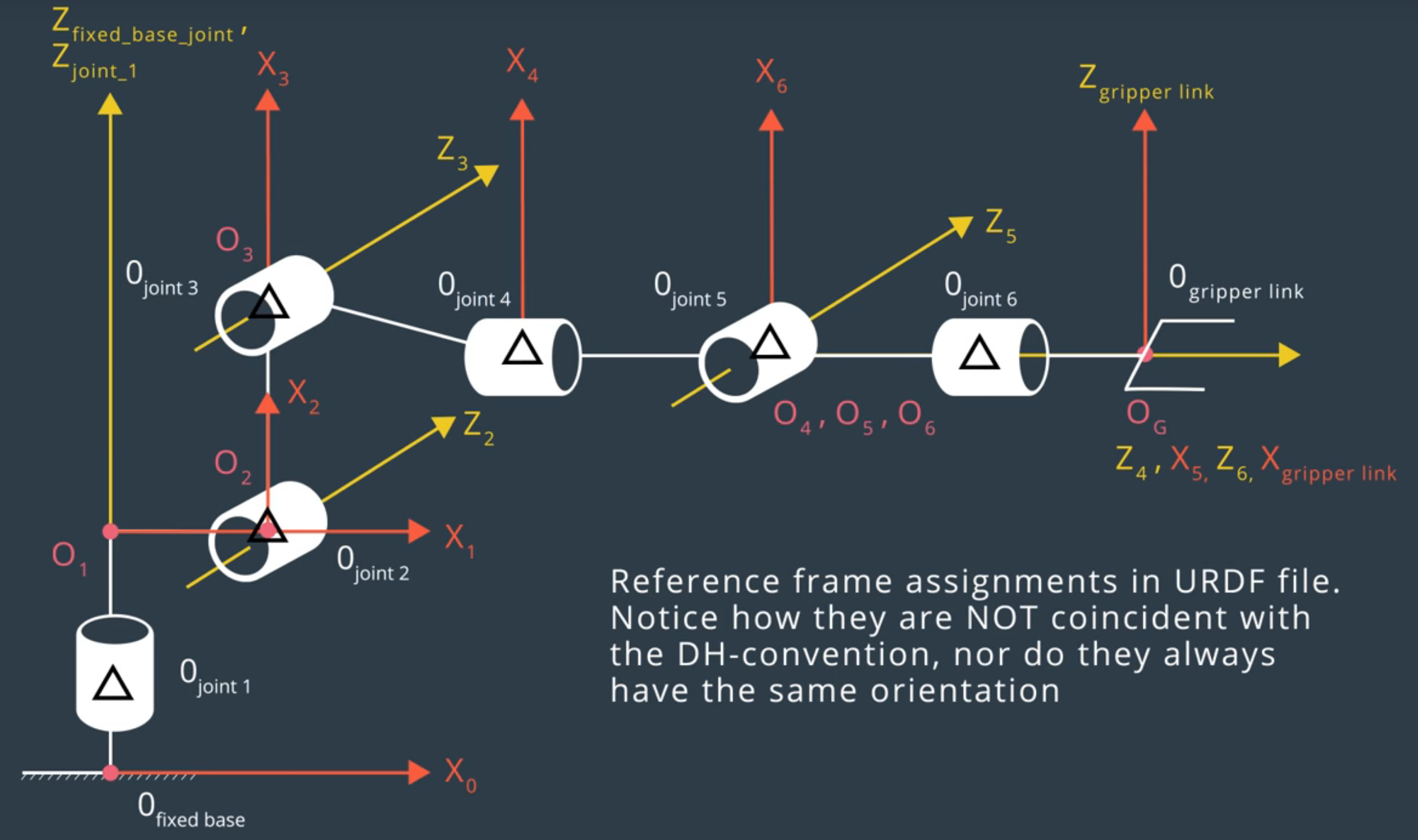
And the table is
| Links | alpha(i-1) | a(i-1) | d(i-1) | theta(i) |
|---|---|---|---|---|
| 0->1 | 0 | 0 | 0.75 | qi |
| 1->2 | - pi/2 | 0.35 | 0 | -pi/2 + q2 |
| 2->3 | 0 | 1.25 | 0 | q3 |
| 3->4 | - pi/2 | -0.054 | 1.5 | q4 |
| 4->5 | pi/2 | 0 | 0 | q5 |
| 5->6 | -pi/2 | 0 | 0 | q6 |
| 6->EE | 0 | 0 | 0.303 | 0 |
kr210.urdf.xacro file shows the relative position between current joint and its parent joint. The choice of x-y-z axis for each frame follows the rules of minimizing the number of non-zero parameters.
For example, the d value of joint 1 can be chosen to be 0.33 or other arbitrary number. But it is better to choose x1 axis to be intersected with next joint, which can reduce the number of non-zero parameters. As a result, D is chosen to be 0.75 for joint 1.
To run the code
# change the flag of "inverse_kinematics.launch" to false
$ cd ~/catkin_ws/src/RoboND-Kinematics-Project/kuka_arm/scripts
$ ./safe_spawner.sh  #
# open another terminal
$ rosrun kuka_arm IK_server.py